
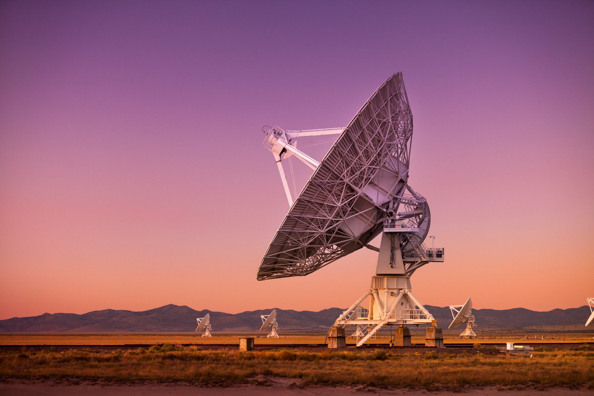
RF Testing in SATCOM Manufacturing
In the manufacturing of SATCOM devices, a variety of RF (radio frequency) tests are performed to ensure that the devices meet performance specifications and are reliable under operational conditions. Here are some common RF tests conducted during the manufacturing process:
Return Loss and VSWR (Voltage Standing Wave Ratio) Measurement
- Purpose: To evaluate the impedance matching of the device and ensure minimal signal reflection.
- Method: Measure the return loss and calculate the VSWR using a network analyzer. These parameters indicate how well the device is matched to the system impedance (typically 50 ohms).
S-Parameter Measurements
- Purpose: To characterize the linear network parameters of the device.
- Method: Using a vector network analyzer (VNA), measure the scattering parameters (S-parameters), which describe how RF signals behave when they encounter the device. Key parameters include S11 (input reflection coefficient) and S21 (forward transmission coefficient).
Gain and Gain Flatness
- Purpose: To determine the amplification factor of the device and its consistency across the operating frequency range.
- Method: Measure the gain (ratio of output signal power to input signal power) at various frequencies within the operating band to ensure it meets specifications and is flat across the band.
Noise Figure (NF) Measurement
- Purpose: To assess the noise performance of the device, which is critical for low-noise amplifiers (LNAs) and receivers.
- Method: Measure the noise figure using a noise figure analyzer or a spectrum analyzer with a noise source. The noise figure indicates how much noise the device adds to the signal.
Third-Order Intercept Point (IP3) and Intermodulation Distortion (IMD)
- Purpose: To evaluate the linearity and distortion characteristics of the device.
- Method: Apply two closely spaced tones and measure the output power of the fundamental and intermodulation products using a spectrum analyzer. The IP3 is a figure of merit for the linearity of the device.
Output Power and Power Added Efficiency (PAE)
- Purpose: To measure the output power of the device and its efficiency in converting DC power into RF power.
- Method: Measure the output power at various input power levels and calculate the PAE, which is the ratio of the RF output power to the total DC power consumed.
Phase Noise Measurement
- Purpose: To assess the stability and purity of the signal generated by oscillators and synthesizers.
- Method: Measure the phase noise using a phase noise analyzer or spectrum analyzer, typically at offset frequencies from the carrier.
Frequency Response and Bandwidth
- Purpose: To determine the operating frequency range and bandwidth of the device.
- Method: Sweep the input frequency and measure the output response using a network analyzer or spectrum analyzer to determine the -3 dB bandwidth.
Harmonic and Spurious Emissions
- Purpose: To ensure that the device does not generate unwanted harmonic or spurious signals that can interfere with other communications.
- Method: Measure the output spectrum using a spectrum analyzer and check for harmonics and spurious emissions relative to the fundamental signal.
Modulation Accuracy and Error Vector Magnitude (EVM)
- Purpose: To evaluate the accuracy of the modulation process, which is critical for digital communication systems.
- Method: Generate a modulated signal and measure the EVM using a vector signal analyzer. EVM quantifies the difference between the ideal and actual signal constellation points.
Time Domain Reflectometry (TDR)
- Purpose: To identify impedance discontinuities and locate faults in transmission lines.
- Method: Send a fast pulse down the transmission line and measure the reflections using a TDR analyzer to detect and locate impedance mismatches or faults.
Summary
Performing these RF tests ensures that SATCOM devices meet stringent performance requirements and are reliable in real-world applications. The tests typically involve sophisticated equipment like vector network analyzers, spectrum analyzers, noise figure analyzers, and signal generators. Ensuring accuracy and repeatability in these measurements is critical, and this often involves automated test setups and careful calibration of test equipment.
Any Questions?
We are here to help!
Email:
info@aurumautomation.io
Offices:
Suite 501 - 77 City Centre Drive,
Mississauga, ON, Canada L5B 1M5
Telephone: 1-416-720-7895
Contact Us
Authorized by the Association of Professional Engineers of Ontario to offer professional engineering services.